
GM
GEORGE MCPHERSON
DESIGN
Development
HUMAN FACTORS
HUMAN FACTORS is the study of human interacion with a product. This includes looking into the usability of the product, by studying anthropometrics and creating a task analysis. Furthermore what makes a product desirable and whether it is 'pleasureable'.
MATERIALS SELECTION
Each of the stages of design requires decisions about the materials of which the product is to be made and the process of making it. Normally, the choice of materials is dictated by the design. But sometimes it is the other way round. The new product , or the evolution of the existing one, was suggested or made possible by a new material. Material selction in mechanical design, Ashby.
My materials analysis poster (left) shows the part of my design I looked into and what I thought the best material was for the manufacture of this component. I looked into the characteristics of polypropylene and how it compares to similar materials. All of this infomation was found on CES EduPack 2014.
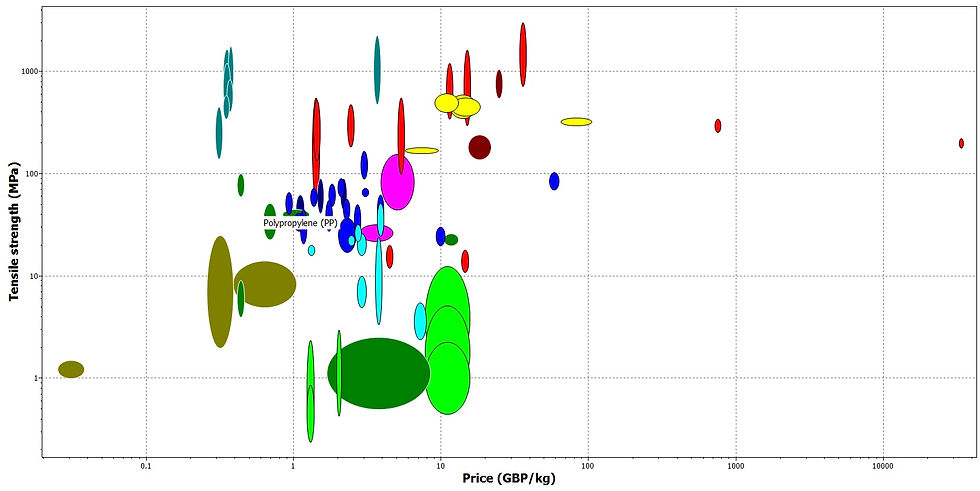
As you can see on the graph polypropylene is labelled and shows that compared to similar materials and plastics polypropylene manages to keep a high tensile strength whilst being affordable. These are both required characteristics of my product.

Polypropylene is labelled, It shows that it has a good tensile strength when it is less dense than other similar materials. The benefit of of this is that polypropylene is lighter, which is important to my design

REVERSE ENGINEERING

The product I took apart for my reverse engineering analysis was a Kenwood FP190 blender. The image to the left shows all 12 parts layed out and labelled. This allowed me to analyse the product to work out all of its specifications.
Reverse engineering is defined as the taking apart of an object to see how it works and how it was manufactured. From reverse engineering I have managed to find out all of the electrical and mechanical specifications that can be applied to design. As well as the materials used in manufacture and how they were processed.

Kenwood Blender

Personal Alarm
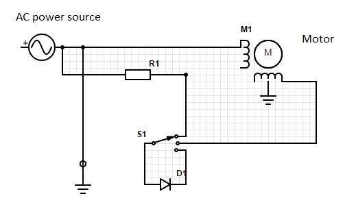
The advantage of a schematic drawing is that it shows all the electronic parts and how they are interconnected in an easy to follow format. My drawing shows the motor and the AC power supply which are both grounded. It also has a three way switch to illustrate the three settings of the blender for various speeds. The final component shown is a resistor which was seen in the blender's circuit.
SOLID WORKS MODELS
 |  |  |
|---|---|---|
 |  |  |
 |  Chosen Design |  Assembly view |
 Assembly |  sensor box |  sensor box 2 |
 sensor box 3 |  Chosen Idea |  cr2032 battery |
 cr2032 battery |  Existing alarm fob |
TECHNICAL DRAWINGS
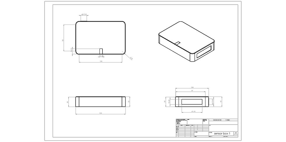
Design shelled so you could see where all the internal components would be placed.

Overall width of this design was too small.

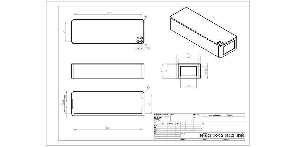
Final technical drawing

This drawing has the BS8888: 2013 standard for Technical documentation and specification. The part would be manufactured through injection moulding out of polypropylene pellets. All measurements are in mm.
5 'THINGS'

Laser Cut Spatula
The shape of the spatula was drawn on solid works so the measurements were accurate. Only a 2D drawing was required so it could be sent to the laser cutter to be cut out of 3mm acrylic. To get the required 30 and 45 degree bends a strip heater was used. Discs of MDF were cut to manufacture an ergonomic handle for the spatula.
The images show the final complete spatula with handle, as well as two solid works drawings of the spatula, one with measurements. The final image is a rough sketch of the spatula.


Clay Overlay Mouse
Using a template, the shape of the mouse was cut out on the band saw from blue foam. The desired shape could be sanded to create an ergonomic design. Modelling clay was rolled out to the specific thickness, and then with one side of the clay tacky it was placed on top of the foam. Using water the clay could then be moulded to the correct shape. This was placed in the oven to dry so it could be sanded to the correct finish. I then sprayed the mouse matte black.
The images show my final sprayed mouse from three different angles, this allows you to see all the shapes and curves that make the design ergonomic and comfortable to hold. Next to these images is a rough sketch of my mouse.


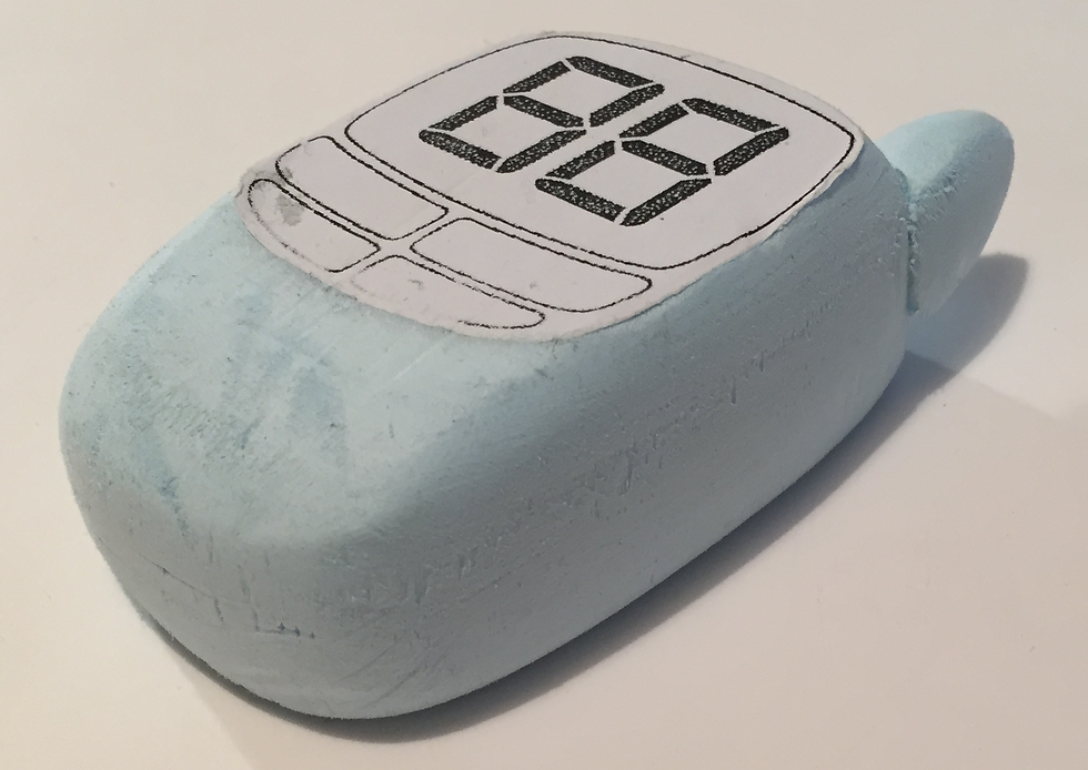
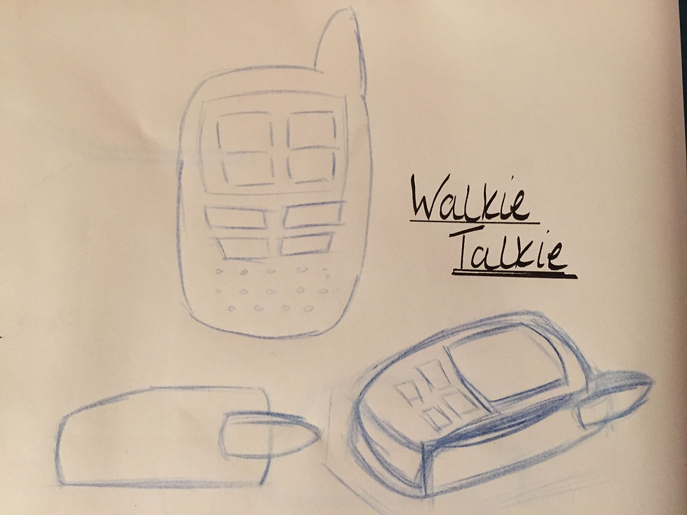
Foam Walkie Talkie
Using a paper template, the basic shape of the walkie talkie could be achieved for both the main body and antenna. The shape was cut on the band saw and then sanded till the desired shape and finish was achieved.
A template was made for the antenna as well, the basic shape of this was also cut on the band saw. This could then be sanded down until it was a smooth continuous shape. The two pieces were glued together to complete the Walkie Talkie.
The images show two angles of the complete walkie talkie with the screen and button tempate attached. Then a rough sketch of the walkie talkie.


Filler Sander Block
Specific layers of MDF were glued together using PVA, making sure they were in the correct order. The 45 degree chamfer was achieved by marking out the angle and then using the disc sander. To get the curved edge on the top side this was also marked out and then sanded by hand. The second curve was achieved by applying filler into the area and smoothing it out to a specific radius. This was left to dry and sanded down until smooth.
The images show the final complete filler sander block from two angles, as well as two solid works drawings of the filler sander block, one with measurements. The final image is a rough sketch of the filler sander block.


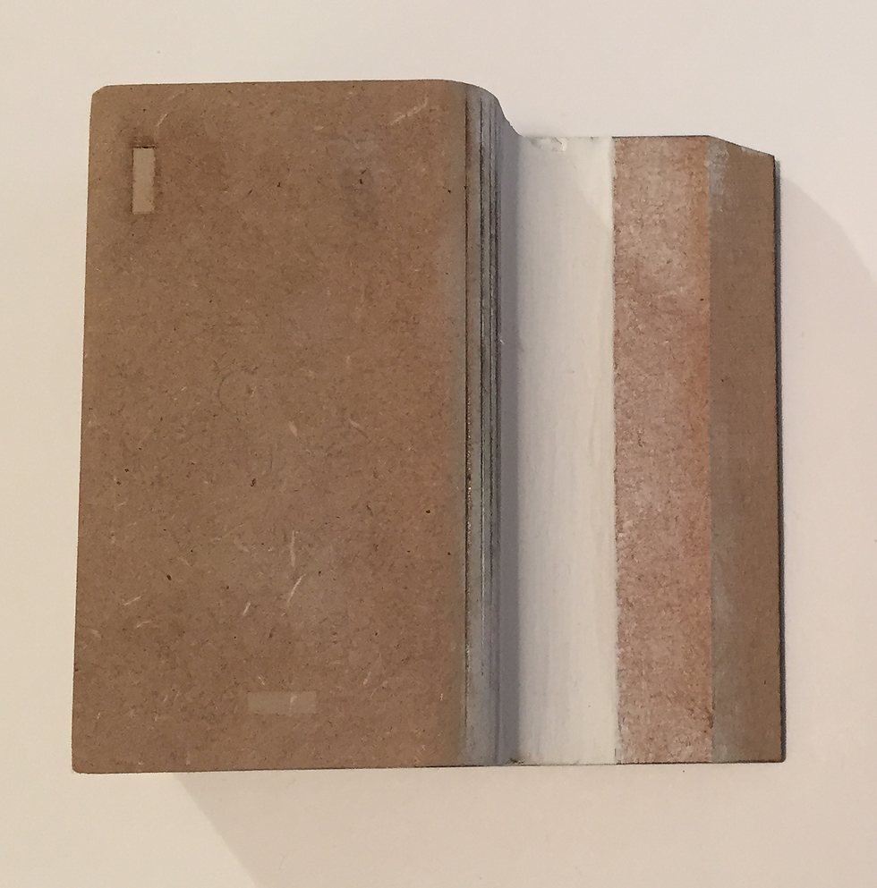
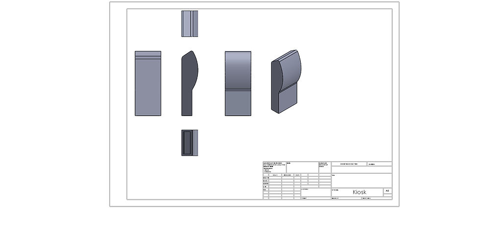
Foam Board Kiosk
Using a paper template the required sides of the kiosk were traced onto a piece of foam board. This could then be cut out using a scalpel and a steel ruler. On certain sides joints needed to be cut as well as notches to allow the foam board to bend to the correct shape. All the pieces were glued together with a glue gun. Two parts of the kiosk have to be assembled separately, the front and the back. Once both were complete they could be glued together.
The images show the final complete foam board kiosk, as well as two solid works drawings of the kiosk, one with measurements. The final image is a rough sketch of the foam board kiosk.
Prototypes

Laser Cut and layered out of 9mm MDF

Laser Cut and layered out of 9mm MDF

3D printed and shelled
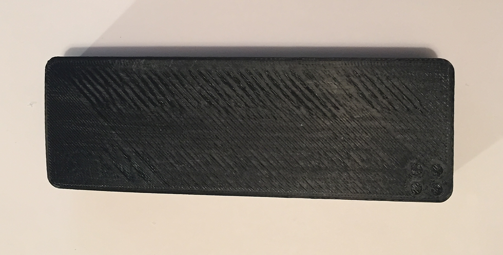
3D printed and shelled

From left to right 1. laser cut MDF 2.3D printed ABS 3. laser cut acrylic
Prototypes were made to see what would be the best way to manufacture my final prototype. For the sensor box I chose to laser cut 9mm MDF because less time was required and a better desired finish was achieved. When it came to the key fob I decided to laser cut three layers, sandwiching a coloured piece of acrylic between two pieces of 2mm MDF. I found this way more accuate and allowed me to give the design a eye catching highlight through the product.
Final Prototype
